Titanium fabrication in China
PA is a quality endorsed Titanium Fabrication company specialising in the products made from titanium. Servicing a variety of industries and applications including civil engineering, medical and consumer goods. Our manufacturing capabilities extend from the production of small and complex titanium alloy components right through to large structures. PA is leading the industry in the design and manufacture of high tolerance and high reliability components for chlor-alkali industry.
Fabrication Capabilities
We can handle it all, design of the production tools, prototyping and mass production. Large and complex parts, post machining and assembly. Our customers receive packaged part, assembly or private label product.
Accredited Titanium Fabrication facilities in China
ISO Certified facility’s, technical support 24/7, dedicated account manager and competitive pricing makes us a manufacturer of the choice. We offer free design analysis and off tool samples.
3 EASY steps to get started!

Send us email
Fill in detail in the form below and send. One of our Engineers will come back to you promptly asking for drawings and technical specifications.

Review quote
You will promptly receive the quote for your project. Review and comment on technical aspects and pricing. We eager to hear your feedback!

Place the order
Our engineers will produce, inspect and pack your order! We can supply material and assembly certification on request.
Ordering process
Your part drawings will be reviewed in house by engineers. The consideration will be around the shape of the titanium part, intended use of the part and type of alloy it will be made of. Some design considerations, such as wall thickness, tolerances may need to be taken into account when using different types of titanium alloys. Off-tool samples will be provided to you after drawings are approved and tool was produced if nesesary.
Been a China based titanium fabricator an important part of our business is short runs and small quantities of custom shapes which include but is not limited to building & construction, transportation, consumer goods, packaging and engineering products.
Value Added Processes
Our team of engineers specialize in mechanical assembly of titanium components in to complete product. We are experienced with a large variety of assembly from simple one or two part additions to complete complex builds involving welding, air-tight modules and electro-chemical devises. Additional services also include but not limited to Anodizing, Painting, Electrical assembly, Testing for functionality and custom packaging.
Titanium Fabrication – overview
Titanium offers an excellent combination of mechanical properties and corrosion resistance. These features, coupled with availability of product forms and ease of fabrication, have led to extensive use of titanium and its alloys in chemical process equipment. Titanium is now a standard material of construction for many chemical processes and equipment, and systems are being assembled by a variety of fabricators on a routine basis for use in many other industries.
Successful utilization requires careful consideration of titanium’s unique characteristics at the design stage as well as during fabrication. Factors such as titanium’s high strength to weight ratio, low elastic modulus, corrosion and erosion resistance, its tendency toward galling, and its reactivity at high temperatures must be considered in order to optimize designs in titanium. It is generally best to start fresh with titanium’s properties in mind instead of attempting to simply substitute titanium for other materials previously used. Fabricators who routinely work with titanium will be helpful in optimizing design of titanium fabrication equipment. The following sections address some aspects of the design, fabrication and maintenance of titanium equipment. Design of titanium equipment has followed traditional standards established for other materials of construction. ASTM mill product specifications, TEMA and ASME Code standards are followed in fabrication. Standard product forms are readily available.
Designing titanium structures
The successful design of titanium equipment begins with consideration of the environment to which the equipment is to be exposed. The corrodents present and maximum operating temperature (under upset conditions, possibly) will dictate which TIMET alloy should be selected. The physical and mechanical properties of the alloy selected may, in turn, dictate some design features. For example, the ductility of an alloy limits the minimum bend radius which is feasible for sheet, plate or tubing. It will also be advantageous to incorporate standard product forms into designs utilizing titanium. The excellent corrosion resistance of titanium often permits a zero corrosion allowance to be specified. Wall thickness for vessels and heat exchanger tubing, therefore, is normally less than would be required for other materials.
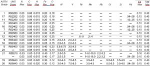
Titanium chemical composition
The chemical compositions of titanium alloys used in industrial applications are in Table below
Stress limits
Maximum allowable stress values as set forth by the ASME Boiler and Pressure Vessel Code, Section VIII-Division 1 (prior to 1995); Section II, Part D (since 1995) are given in Table below. These values are obtained using the prescribed ASME Boiler Code Procedure, i.e., the lesser of one fourth of the ultimate tensile strength or one third of the 2% offset yield strength at each given temperature. Various product forms of annealed ASTM Grade alloys are covered in this table. Design stress intensity values for Section VIII-Division 2 construction are given in Table below. Figures are for determining shell thickness of cylindrical and spherical vessels under external pressure when constructed of Gr. 2, Gr. 3, following ASME procedures.
Calculating shell thickness of cylindrical and spherical vessel under external pressure. Material of construction is Gr.2 unalloyed titanium.
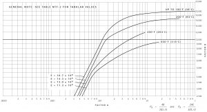
Safe external working pressures for annealed Gr. 2 welded tubing of various diameters and wall thickness for temperatures up to 100°F (38°C) are in Table below. The multiplying factors offered in Table to follow allow calculation of safe internal pressures for welded tubing for other alloys and to temperatures as high as 600°F (316°C). The data in Tables 5 and 6 can be used to select the minimum wall thickness of welded tubing required for internal pressure and temperature conditions anticipated in heat exchanger service. Unlike many other materials, a corrosion allowance is usually not required for titanium. This permits thinner-walled tubing to be used than is generally practical with other materials.
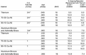
Tube vibration in a heat exchanger occurs when shellside cross flow velocity is too high and baffle spacing is too distant. Excessive tube vibration may result in fatigue failures at support plates or in midspan collision damage. Titanium’s hardness and corrosion fatigue resistance act to minimize vibration damage, but its lower modulus (than steel or copper-nickel alloys) must be considered in design to keep deflection within acceptable limits. Proper baffle design and spacing should be incorporated into the designs of both new and retrofit titanium tube bundles to avoid flow induced vibration. A comparison of static deflections for titanium tubing and other materials and the reduction in baffle spacing required when using titanium tubes is shown in Table 7. The data illustrate that a reduction in baffle space is more effective than an increase in wall thickness in decreasing deflection. Generally, if vibration has not been a problem in a heat exchanger, re-tubing with titanium using proper baffle spacing will eliminate flow induced vibration as a potential problem.
Welded tubing safe external working pressure in PSI at 38c. Annealed Gr.2, 7 and 16.


The thermal conductivity of titanium is roughly 50% higher than 304 stainless steel.. This contributes to its excellent heat transfer properties. The overall heat transfer coefficient, U (Btu/hr.-ft 2-°F), indicates the ability of a surface to transfer heat from one flowing fluid on one side to another fluid on the opposite side. The inverse of the coefficient, (1/U), can be considered to be the total resistance to heat flow which, as indicated in Figure 3, is made up of five component resistances: tube- side fluid, rt, tube-side fouling, rtf, tube metal, rm, shell-side fouling, rsf, and shell-side fluid, rs. An ideal tube material will resist fouling (minimizing rtf and rsf), permit high tube side velocities (minimizing rt), and be usable in thinnest section (minimizing rm). A zero corrosion allowance can often be specified for titanium. This, coupled with adequate strength, permits titanium tubing to be used with unusually thin walls.
Thermal conductivity compared:

The high resistance of titanium to corrosion prevents buildup of corrosion products which rob other metals of heat transfer efficiency. Titanium’s hard, smooth surface also minimizes buildup of external fouling films and makes cleaning and maintenance easier. The excellent resistance of titanium to turbulence and erosion-corrosion permits use of relatively high flow rates of 18-22 ft./sec. in silt-laden seawater or even up to 100 ft./sec. in clean seawater without damage to the passive oxide film. Tests in 80°F (27°C) sea water for 60 days at 25 ft./sec. have shown titanium’s corrosion-erosion resistance to be 80 times better than that of the next-best material, a copper-nickel alloy. Other tests in 85°F (29°C) sea water for 60 days at 27 ft./sec. proved titanium to be almost 100 times better than stainless steel, the next-best material.
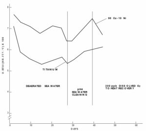
Putting it all together – the resulting overall heat transfer rate of titanium surfaces is often comparable to that of metals with higher thermal conductivity. The data in Figure 5, for instance, illustrates that the overall heat transfer coefficient of titanium in a desalination environment equalizes to that of 90-10 copper nickel after a short operating period. The copper-nickel alloy, due to its higher thermal conductivity, had a higher overall heat transfer coefficient when first placed in service with clean surfaces. However, as fouling due to corrosion product proceeded on the 90-10 alloy with time, the heat transfer coefficient dropped to a value equal to that of titanium which did not experience corrosion product fouling. In these tests, sea water moved at 5 ft./sec. inside 3/4 ” x 18 gauge tubes and steam was condensing on the outside. Had thin-walled titanium tubing been used as is present practice, the heat transfer coefficient for titanium would have been higher than that of the copper-nickel alloy almost from the start. A variety of process equipment has been fabricated of solid titanium, titanium-clad steel, and with titanium linings. Choice of one construction over another depends on several factors, among them the environment, the feasibility of manufacture and cost. Consultation with experienced titanium fabrication engineers will facilitate selection.
Solid Titanium
Solid construction is in many cases the most straight-forward and economical fabrication approach for titanium equipment. This appears to be particularly applicable for equipment which will be subjected to vacuum, when thermal cycling is frequent, when internals must be positioned inside a vessel, and when the wall of the equipment is moderately light, i.e., on the order of up to 3/4-inch in thickness. It may be more economical to utilize clad construction for heavier wall thickness.
Clad Construction
When pressure and temperature conditions dictate a need for wall thickness of one inch or greater, titanium-clad steel may be the desired approach. Large plates with a thin titanium layer explosively bonded to steel are available. With the titanium providing the necessary corrosion resistance, the lower cost carbon steel provides strength. Explosive cladding produces a metallurgical bond which transfers heat far better than a loose liner. The clad product also enables thermal cycling without fear of separation of the two metals. Welding of clad product requires special techniques which first involve joining and inspection of the carbon steel followed by joining of the titanium layer. Care to prevent contamination of the titanium by iron or by air must be exercised.
Heat transfer coefficient for brine heater 82-107c. OD 0.750, wall thickness 0.49inch:
Titanium Linings
Titanium linings can be used in equipment which will not operate under a vacuum and whose maximum operating temperature does not exceed about 400°F (204°C). Once again, the titanium liner provides the corrosion resistance while a cheaper metal, usually steel, contributes strength. Several lining methods have been used which utilize titanium. These include: loose-fit linings, mechanical or weld- fastened linings, and linings expanded into place inside the equipment. Experienced fabricators will be helpful in selecting the proper technique. In general, lining is not recommended for equipment to be operated above 400°F (204°C). The thermal expansion of titanium is less than that of steel. Differential expansion can cause stresses which on thermal cycling may cause fracture of the lining, particularly in large equipment.
Loose Linings
As the term implies, a thin titanium lining is fabricated to the required configuration and is then positioned in the intended equipment. Flanges are generally used to prevent the lining from moving. Generally, a gasket material is used between mating flanges.
|
|||||||||||||||||||||||||||||||||||||||||||||
Loose linings are the least costly method and are used in small to medium-sized equipment which is not subject to pressure or vacuum. Process piping, utility chimneys (stacks) and ducting are typical examples where loose linings have been used. Futher information on installing linings is contained in the NACE (National Association of Corrosion Engineers) Standard Recommended Practice RP0292-92 (revised 1997), Item No. 53088 “ Installation of Thin Metallic Wallpaper Lining in Air Pollution Control and Other Process Equipment ” .
Welded or Bolted Linings
If equipment to be lined is to be subjected to internal pressures, the lining must be installed to prevent collapse in the event of accidental loss of pressure. Although not used extensively, a vanadium interlayer or silver braze interlayer can be used to weld titanium to carbon steel. Another lining method for consideration involves resistance welding titanium to a substrate. This method has been used extensively in attaching titanium to flue gas desulfurization stacks and is more economical than explosive bonding. The steel substrate acts as the strength member for attaching the lining to a steel substructure by welding. The titanium is seal welded to provide an impervious barrier to the corrosive atmosphere. This lining method allows for an air gap between the titanium and substrate. Titanium bolts have also been used to attach titanium linings, particularly where a cement only substrate exists (with no metallic inner C-steel liner). Mechanical fastening serves two purposes: to take some of the stresses from welds, and to anchor the lining in a vessel where pressures are to be employed.
Selection of a tubesheet material for use with titanium tubes in a heat exchanger depends on several factors. Tubesheets can be solid titanium, explosively clad titanium on steel, loose lined titanium on steel, or a dissimilar metal. Solid tubesheets are used primarily in all-titanium tubed units. Design follows conventional practice. Either explosively clad tubesheets or loose liners are used with steel or other dissimilar metal shells. Loose liners offer economic use of material and are easy to maintain and fabricate. When explosively clad or loose lined tubesheets are used, the tubes must be seal welded to prevent minor tubeside leakage from reaching the steel, causing undetectable corrosion. Seal welding is usually not required if solid tubesheets are used [for tubes .025 inch wall (23 BWG) and heavier]. If titanium tubes are to be inserted into dissimilar metal tubesheets, as is often the case in retubing jobs, the possibility of galvanic corrosion must be considered. In actual practice, titanium tubes have been used with a variety of tubesheet materials as indicated in table above.
Generally, titanium is more noble than most of the commonly used tubesheet materials. Galvanic corrosion might, therefore, be expected on the dissimilar metal but not on titanium. For sea water service, metals close to titanium in the galvanic series are recommended if titanium or titanium-clad tubesheets are not used. Nickel Aluminum Bronze (CDA Alloy 6300) or nickel/copper Alloy 400 have proven to be acceptable. Sufficient strength to resist deformation of ligaments during roller expansion of titanium tubes should be present in the material of choice. If galvanic corrosion appears likely in a given situation, some protective measures can be taken. These include insulation of the titanium from contact with dissimilar metals, proper use of cathodic protection or sacrificial anodes (zinc or magnesium anodes should not be used), and use of coatings. Epoxy coatings have been used on some tubesheets tubed with titanium in power plants. However, little experience is available from the chemical process industries, presumably because of the more severe conditions encountered. Some favorable experience is reported for polysulfide rubber and filled resin coatings in preventing galvanic corrosion on tubesheets in oil refinery environments overseas. Use of an all titanium tube bundle will eliminate the possibility of premature removal of a bundle from service due to tubesheet galvanic corrosion failure. If seal welding of tubes to tubesheets is required, solid titanium or titanium-clad tubesheets must be used.
Gasket Materials
A variety of gasket materials have been used in titanium equipment. A key consideration in selecting a gasket material is the environment to which it will be exposed. Manufacturers of gasket materials should be consulted for recommended materials to withstand the conditions of temperature and corrosives being considered. From the titanium viewpoint, prevention of crevices is important. Materials which give elastically, rather than creep, will seal tightly, thereby minimizing crevices. The rubbers – such as natural or butyl – have given good results and are to be preferred over non-yielding materials. Teflon, with its tendency to creep, requires heavy flanges to maintain tight joints.
Design for Welding Access and Distortion
When designing equipment to be fabricated of titanium, consideration must be given to providing proper access during welding. Designs must provide space for manipulation of the torches and trailing shields, which are necessary equipment for welding titanium, particularly where nozzles or attachments are close to large flanges. Full access to the root side of welds is also desirable for titanium equipment. This stems from the necessity for inert gas shielding and inspection of titanium welds. If a weld joint cannot be reached, both inspection and repair are made more difficult. Titanium tends to shrink and distort more than steel during welding. The low thermal conductivity of titanium results in high metal temperatures and, consequently, loss of strength. Titanium tack welds, weld metal deposits and abutting edges soften and move more than would be expected for steel. Measures need to be taken to maintain joint alignment. In addition, designs should employ balanced (two sided) welds wherever possible. Tee joints with full penetration groove and fillet on the same side of the joint should be avoided if possible.
The fabrication of titanium product forms into complex shapes is routine for many fabricators. These shops recognized long ago that titanium is not an exotic material requiring exotic fabrication techniques. They quickly learned that titanium is handled much like other high performance engineering materials, provided titanium’s unique properties are taken into consideration. Important differences between titanium and steel or nickel-base alloys need to be recognized. These are:
- titanium’s lower density
- titanium’s lower modulus of elasticity
- titanium’s higher melting point
- titanium’s lower ductility
- titanium’s propensity to gall
- titanium’s sensitivity toward contamination during welding
Compensation for these differences allows titanium to be fabricated, using techniques similar to those with stainless steel or nickel-base alloys. The following sections deal with common operations used in fabricating titanium. The information given is intended to be used as guidelines. It is by no means exhaustive. Further information is available from TIMET and from experienced titanium fabricators.
Work Area
The fabrication of titanium demands attention to cleanliness. It is not uncommon for shops which handle several metals to isolate an area to be used especially for titanium. Welding, in particular, requires freedom from contaminants which might degrade the properties of titanium. Thus, the area set aside for titanium should be free of air drafts, moisture, dust, grease and other contaminants which might find their way into the weld metal.
Shearing
The annealed industrial titanium alloys can be sheared using capacity limitations applicable to 300 series stainless steels. Sheared edges on plate over 3/8-inch in thickness should be inspected for cracks. Filing the sheared edge in preparation for welding is good practice to prevent entrapment of contaminants which might degrade weld properties.
Flame cutting
Oxy-gas cutting processes (including oxy-acetylene), useful for steel, can also be used on titanium. Smaller cutting tips and higher travel speeds can be employed. The cut edge on titanium is contaminated with oxygen and carbon and must be removed by grinding or machining. It is recommended that a minimum of 1/16-inch of metal below the lowest point of the cut roughness be removed. Cutting allowances will include about 1/8-inch for kerf, plus 1/16-inch for roughness, plus a minimum of 1/16-inch for removal of contamination. Thick plate will require larger allowances. The contaminated cut surface is extremely hard. If machining is to be used to remove the contamination, the tool point must penetrate beneath the contaminated layer or tool life will be short.
Caution: Torch cutting of titanium produces large volumes of white, titanium dioxide smoke, which must be vented. In addition, the cutting discharge is extremely hot and brilliant. Measures should be taken to prevent damage from the discharge. Operators should wear dark glasses and full face protection.
Sawing
Mechanical hacksawing of titanium is very common. Coarse saw blades, heavy feed and generous amounts of water soluble oil coolant are recommended. Titanium is also readily friction cut. Such surfaces should be filed to remove about 0.005 inches of contamination. Similarly, abrasive cutting of titanium is satisfactory if coolant is used and contaminated layer is removed by filing.
Hand abrasive grinding
A clean wheel, used only on titanium is important. An open type wheel containing large grains has been found to minimize clogging. Excessive buildup of heat should be avoided to minimize metal contamination. Ground surfaces should be filed or mechanically finished to remove abrasive particles and, in particular, any visible metal oxide (burns). Sandpaper or steel wool should be avoided and wheel type mechanical burrs (rotary files) should be operated at low rpm to avoid burning and maximize tool life. When grinding is used on titanium, measures must be taken to protect adjacent titanium surfaces and surroundings from the extremely hot grinding sparks.
Machining Titanium
Machining techniques for titanium are no more difficult than those for other high performance metals; for instance the austenitic stainless steels. Reasonable production rates and excellent surface finish are readily attainable on machined parts, provided some unique characteristics of titanium are taken into account. These characteristics are:
- The unusual chip-forming tendency and low thermal conductivity of titanium tends to cause a build-up of heat on the edge and face of cutting
- The reactivity of titanium with cutting tools contributes to seizing, galling, abrasion and pick up on cutting edges and
- The low elastic modulus of titanium permits greater deflections of workpieces and, therefore, may require proper
Machining conditions can be selected which minimize or circumvent the adverse effects of these characteristics of titanium, thereby allowing good tool life at acceptable production rates.
Observation of the following six guidelines will aid in successfully machining titanium:
- Use low cutting Tool tip temperature is strongly affected by cutting speed. A low cutting speed helps to minimize tool edge temperature and maximize tool life. Lower speeds are required for titanium alloys such as Gr. 5 than for unalloyed titanium.
- Maintain high feed rates. Tool temperature is affected less by feed rate than by speed. Therefore, the highest rate of feed consistent with good practice should be The depth of cut should be greater than the work hardened layer resulting from the previous cut.
- Use a generous quantity of cutting The coolant carries away heat in addition to washing away chips and reducing cutting forces, thereby improving tool life.
- Maintain sharp tools. Tool wear results in build-up of metal on cutting edges and causes poor surface finish, tearing and deflection of the workpiece.
- Never stop feeding while tool and work are in moving contact. Permitting a tool to dwell in moving contact with titanium causes work hardening and promotes smearing, galling and seizing, which may lead to total tool
- Use rigid Rigidity of machine tool and workpiece ensures a controlled depth of cut.
Tool Materials
Cutting tools for titanium require abrasion resistance and adequate hot hardness. Carbide tools (such as Grades C-2 and C-3), where feasible, will optimize production rates. The general-purpose high speed tool steels (such as Grades M1, M2, M7, and M10) are often suitable for machining titanium. However, best results are generally obtained with more highly alloyed grades (such as T5, T15, M33, or the M40 series).
Cutting Fluids
Correct use of coolants during machining operations on titanium will greatly increase cutting tool life. Chemically active cutting fluids transfer heat efficiently and reduce cutting forces between tool and workpiece. The result is prolonged tool life. Large quantities of cutting fluid are needed to keep the titanium workpiece and the cutting tool cool during high speed machining operations. Water base fluids are more efficient than oils. A weak solution of rust inhibitor and/or water soluble oil (5 to 10 percent) is the most practical fluid for high speed cutting operations. Slow speed and complex operations may require chlorinated or sulfurized oils to minimize frictional forces and reduce the galling and seizing tendency of titanium. Best tool life in intermediate speed operations may be achieved by utilizing a good coolant containing a chemically active additive. If chlorinated cutting fluids are used on alloys which may be subject to stress corrosion cracking, carefully controlled post-machining cleaning operations must be followed.
Turning of Titanium
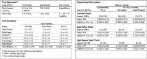
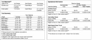
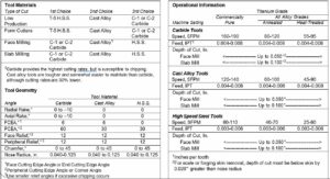
Turning is the simplest machining operation for titanium and its alloys. Through proper machine parameters and use of coolant, surface finishes of 20 to 30 microinches RMS are obtainable with ±0.001 inch tolerances. Carbide tools provide highest production rates for continuous turning operations. Interrupted cuts, plunge cuts and grooving are best performed by the softer but tougher high-speed steels or cast alloys. Tools must be resharpened or replaced before final tool failure occurs. An 0.015 ” wearland for carbide tools and 0.030 ” wearland for high-speed steel or cast alloy tools can be used as a guide for halting turning operations. Tool geometry, particularly rake angle, is important. Negative rake angle is recommended for rough turning with carbide tools. Positive rakes are best for finish and semi-finish turning and when high-speed steels or cast alloy tools are used (Figure 6). Large amounts of water-base soluble oils (5 to 10 percent solution) or chemically active (5 percent sodium nitrate in water) coolants are recommended. Sulfo-chlorinated oils may be used, if necessary, at low cutting speeds. A summary of recommended tool geometries and machine parameters are found in Table 10.


Milling Titanium
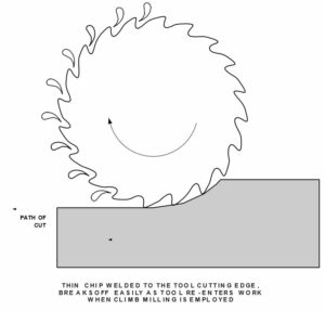
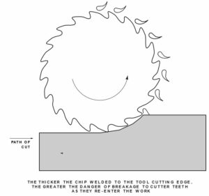
Climb milling should be used where possible to minimize tool chipping (Figures 7 and 8). Slow speeds and uniform, positive feeds help to minimize tool temperature and wear. Tools should not be allowed to dwell in the cut or rub across the workpiece. High speed steel cutters have proved to be satisfactory in milling titanium. Carbide tools give highest production rates but are more susceptible to chipping. Regardless of the tool used, the smallest diameter cutters with the largest number of teeth will minimize deflection and chatter. Increased relief angles, compared to standard cutter angles, increases tool life by reducing pressure, deflection and tendency to load. Water base coolants incorporating rust inhibitors or water soluble oils are best for most milling operations on titanium. Low viscosity sulfo-chlorinated oil may be used when cutting speeds are low. Recommended tool materials, tool angles and machine parameters for face and slab milling of commercially pure and alloy grade titanium in Table 11.
Drilling Titanium
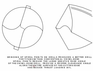
Sharp drills of proper geometry are important in drilling titanium. Heat removal through use of large amounts of coolant and, if practical, heat sinks will help to maintain drill life. Dwell of the drill, which often occurs on hand drilling, should be avoided. Best results are obtained with positive feed equipment. Where practicable, carbide-tipped drills provide optimum life, particularly for deep holes. High-speed steel drills are suitable for many operations. Chromium plating or oxide coating may be useful in resisting galling of the drill margin. Machine ground spiral point configuration is preferable to conventional chisel points (Figure 9).Recommended parameters for drilling titanium are in Table 12. When drilling holes over one diameter deep, the drill should be retracted frequently to clear the drill flutes and hole of chips. Chlorinated or sulfo-chlorinated oils and soluble-oil emulsions are satisfactory as cutting fluids. Oil feeding drills may be required for deep holes.
Tapping Titanium
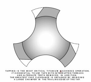
Holes to be tapped must be uniform and free of work hardening. Sharp, clean taps of proper designs are essential. Replacement of taps at the first sign of wear is strongly recommended. Spiral-point, interrupted flute taps with alternate teeth omitted have given good results on titanium when used at slow speeds. Modification of the tap by grinding away the trailing edge of thread is beneficial (Figure 10). High- speed steel taps are generally used. Since 75 percent threads are difficult to obtain with normal cutting speeds, 65 percent threads are recommended wherever possible to maximize tap life. Surface treatments such as black oxide coatings or nitriding can assist in reducing galling tendencies, thereby improving tap life. Paste type cutting compounds (lithopone paste) have given good results. Chlorinated or sulfo-chlorinated oils have also been successfully employed in tapping titanium and its alloys. Tapping speed for titanium should be kept low to minimize heat buildup. Parameters to be used as a guide in tapping operations on titanium and its alloys are in Table 13
Reaming Titanium
When done properly, reaming can provide holes in titanium with a tolerance of +0.002 to -0.000 inches. Reamer margins tend to gall and seize in titanium, but proper tool design and operating conditions effectively eliminate this problem. Sufficient stock must be available to provide continuous cutting and prevent galling and work hardening. High speed steel reamers are generally satisfactory. Carbide reamers allow higher surface speeds or longer tool life. Spiral-flute reamers generally provide longer life than straight-flute reamers. Sulfo-chlorinated oils appear to be the best cutting fluid. However, water-base oil emulsions are also used successfully, particularly with the softer unalloyed titanium grades.
Grinding Titanium
Both abrasive wheel and belt grinding are used on titanium. Metal removal by grinding titanium is low, compared to that of carbon steel. However, under proper conditions, abrasive wear is reasonably low and surface finish of 15 microinches is possible.
Wheel Grinding
Selection of wheel, wheel speed and fluid for grinding titanium is important. For hard wheel grinding, vitrified- bonded wheels are most effective. Aluminum oxide wheels give good results when limited to grinding speeds of 2000 surface feet per minute or less. Silicon carbide wheels can be used at 4000 to 6000 surface feet per minute if higher speeds are desirable. A feed of about 0.001 inch per pass is generally suitable for all wheels. Abrasive grit size of 60 to 80 and wheel hardness of J to L is commonly used. No appreciable sparking accompanies aluminum oxide wheel grinding of titanium. Thus, flooding of the workpiece with standard grinding oils can be used. Water soluble nitrite-amine solutions (rust inhibitors) also work well with aluminum oxide wheels. Silicon carbide wheels, however, operate best with sulfo-chlorinated grinding oils. Complete flooding of the workpiece minimizes possibility of fire. A 10 percent solution of nitride rust inhibitor in water eliminates the risk of fire but is less effective than oil with silicon carbide wheels. Water soluble oils are also useful but are less effective. Some wheel specifications for various grinding operations and parameters are in Table 15. When it is necessary to grind by hand or where coolants cannot be used, care should be taken to provide protection for any nearby personnel or equipment.
Belt Grinding
Coated abrasive grinding of titanium demands attention to selection of the belt, the coolant and operating parameters. Resin-bonded cloth belts with silicon carbide abrasive generally provide best performance. A 50 grit belt is typically used for coarse grinding and a 120 grit or finer belt for finish grinding. Surface finish of 5 to 10 microinches is obtainable in commercial practice. Fluids should always be used when grinding titanium to protect the workpiece and eliminate sparks which might cause fires. Spray and flooding techniques are both used. Water solutions of 15 percent tri-potassium phosphate, or 5 percent potassium or sodium nitrite, have been effective with titanium. Belt grinding performance generally improves with increase in load and decrease in speed. Speeds of the order 1000 to 2000 surface feet per minute and pressures in the vicinity of 100 psi provide optimum productivity and belt life.
Abrasive Cutting
Rubber bonded, 60-grit silicon carbide cutoff wheels flooded with a water solution of 10 percent nitrite-amine (rust inhibitor) have been successfully used with titanium. Machines with oscillating cutting heads give best results. If workpiece diameter is greater than three inches, rotation is recommended to minimize wheel breakage and/ or heat checking. Operating guidelines for abrasive cutting of titanium are in Table 16.
Hacksawing
Rigid setups and water soluble or sulfo-chlorinated cutting fluids are suggested for titanium. Low surface speeds and positive feed, combined with coarsepitched (3, 4 or 6 teeth per inch) high speed steel blades have proved to be effective. Surface scale or contaminated surfaces can cause accelerated blade wear if not removed. Operating guidelines for hacksawing titanium are in Table 17.
Bandsawing
Coarse-pitched (6 teeth per inch), highspeed steel blades, 1-inch wide, employed at speeds of 80 to 90 surface feet per minute have given good results with titanium. Cutting rates on the order of one square inch per minute are optimum. Water soluble or sulfo-chlorinated cutting fluids are required. Rigid setups are required for precision work.
Water Jet and Abrasive Jet Cutting
Commercially pure and alloy titanium is readily cut using water jet and abrasive jet cutting. Ultra high pressure water or abrasive slurries focused in a fine line are used to erode the titanium in thicknesses up to 3 inches and higher. The cut edges are free of contamination and are typically smooth and burr free. This cutting method is particularly applicable when cutting precise intricate shapes, or when cutting brittle materials such as titanium aluminides.
Fire Prevention
Fine particles of titanium can ignite and burn. Use of water-base coolants or large volumes of oil-base coolants generally eliminates dangers of ignition during machining operations. However, accumulation of titanium fines can pose a fire hazard. Chips, turnings and other titanium fines should be collected regularly to prevent undue accumulation, and should always be removed from machines at the end of day. Salvageable material should be placed in covered, labeled, clean, dry steel containers and stored – preferably in an outside yard area. Nonsalvageable fines should be disposed of properly. Titanium sludge should not be permitted to dry out before being removed to an isolated outside location. Dry powders developed for extinguishing combustible metal fires are recommended for control of titanium fires. For maximum safety, such extinguishers should be readily available to each machinist working with titanium. Dry sand retards but does not extinguish titanium fires. Carbon dioxide and chlorinated hydrocarbons are not recommended. Water should never be applied directly to a titanium fire.
|
Forming Titanium
Titanium is readily formed at room temperature, using techniques and equipment suitable for steel. When correct parameters have been established, tolerances similar to those attainable with stainless steel are possible with titanium and its alloys. Recognition of several unique characteristics of titanium will aid in ease of forming:
- The room temperature ductility of titanium and its alloys, as measured by uniform elongation, is generally less than that of other common structural This means that titanium may require more generous bend radii and has lower stretch formability. Hot forming may be required for severe bending or stretch forming operations.
- The modulus of elasticity of titanium is about half that of steel. This causes significant springback after forming titanium for which compensation must be made
- The galling tendency of titanium is greater than that of stainless This necessitates close attention to lubrication in any forming operation in which titanium is in contact (particularly moving contact) with metal fabrication dies or other forming equipment.
Preparation for Forming
Titanium surfaces normally are acceptable for forming operations as received from the mill. Gouges and other surface marks, introduced during handling, should be removed by pickling or sanding. Burred and sharp edges should also be filed smooth before forming to prevent edge cracking.
Cold Forming
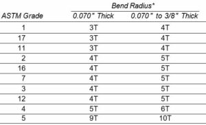
Slow speeds should be used when forming titanium. The degree to which a particular titanium grade or alloy can be formed at room temperature is dependent upon its uniform elongation in a tensile test. The uniform elongation dictates the minimum bend radius as well as the maximum stretch which the alloy can sustain without fracturing. In this respect, annealed Gr. 1, 11 and 17 exhibit maximum formability. Bend radii for these alloys in sheet and plate product form, as defined by ASTM specifications (B265), are in Table 18. The minimum bend radius for any given grade of titanium will typically be about one-half of the ASTM specified bend radius for that grade.
Springback
A loss of 15 to 25 degrees in included bend angle must be expected, due to springback of titanium after forming. The higher the strength of the alloy, the greater the degree of springback to be expected. Compensation for springback is made by overforming. Hot sizing of cold formed titanium alloy parts has been successfully employed. This technique virtually eliminates springback when the hot sizing temperature is high enough to allow stress relief.
Hot Forming
The ductility (bendability and stretch formability) of titanium increases with temperature. Thus, forming operations can be done at elevated temperatures which would be impossible at room temperature. The influence of elevated temperature on bend radius of annealed Gr. 5 sheet is shown in Table 19.
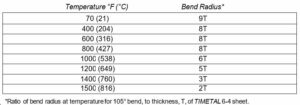
The higher the temperature, the easier the forming. Unalloyed titanium are most readily hot formed in the 400°-600°F (204°-316°C) range with no fear of thermal damage. Springback is virtually eliminated on forming at 1200°F (649°C) and mechanical properties are not affected. Oxidation of surfaces becomes a factor at temperatures exceeding 1100°F (593°C), necessitating a descaling operation. Heating for hot forming can be accomplished by furnace, radiant heater or direct flame impingement (slightly oxidizing flame). Local chilling of heated metal should be avoided to prevent surface checking during forming operations. Allowances in tool design for thermal contraction of warm formed titanium parts may be necessary.
Drawing
Unalloyed titanium is capable of being drawn to depths greater than those attainable with carbon steel. Gr.1, 11, 17 which are most ductile, offer best drawability. Alloys, such as Gr. 5, which have lower ductility, are difficult to draw at room temperature.
Several factors need to be considered before drawing titanium:
- Blanks should be deburred and edges carefully
- Tool surfaces should be polished and absolutely free of
- Blanks should be clean and free of dirt and
- Proper lubrication should be applied to
- The large springback of titanium may require modified die
- Slow drawing speeds produce best
In practice, care must be taken in the drawing of titanium because of titanium’s tendency to gall. Galling not only mars the surface of the titanium drawn part but may also cause failure of the part during the drawing operation. Precautionary steps, therefore, need to be taken to prevent any contact of the titanium with tools and dies by proper lubrication. Conventional drawing lubricants generally are not acceptable for use with titanium. The most effective lubricants appear to be dry-film types incorporating anti-galling constituents. Polyethylene or polypropylene in dry-film or strippable form (0.003 inch thickness) have proven to be effective. A suspension of acrylic resin in trichloroethylene containing molybdenum disulfide and PTFE (polytetrafluoroethylene) coatings have also worked well and appear capable of surviving more than one draw. High-pressure grease-oil type lubricants may also be acceptable at room temperature for mild draws. As with other forming operations, the springback characteristic of titanium needs to be recognized. Tools may have to be designed to compensate for springback, particularly if drawing is to be done at room temperature. Deeper draws, lower loads and less distortion in the finished part are obtainable by drawing titanium hot. Temperatures in the range 400°-600°F (204°-316°C) are best for unalloyed titanium. Titanium alloys, such as Gr. 5 which have low ductility and are difficult to draw at room temperature, often can be drawn hot, in the range of 900°-1200°F (482°-650°C). Hot forming lubricants generally contain graphite or molybdenum disulfide and may be applied over zinc phosphate conversion coatings.
Tube Bending
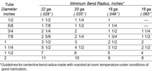
Titanium tubing is routinely bent on conventional tube bending equipment. Mandrel benders are recommended particularly for tight bends. Wiper dies and mandrels should be smooth and well lubricated to minimize titanium’s tendency to gall. Bending should be slow. The minimum bend radii with mandrel for cold bent Gr. 2 tubing are in Table 20. Bends made without a mandrel require larger radii. If smaller radius bends than given in Table 20 are required, it may be necessary to bend the tubing at 400°- 600°F (204°-316°C). Consideration should be given to using heavier wall tubing for tight bends to compensate for thinning which takes place at the tubes outer periphery on bending.
Roller expansion
The most commonly used method of making tube/ tube sheet joints is roller expansion. Roller expansion procedures for titanium tubes into tube sheets are similar to those used for other materials. For best results, the tube sheet holes should be within the limits specified by TEMA (Tubular Exchanger Manufacturers Association) for shell and tube heat exchangers (Table 21) or within the limits specified by HEI (Heat Exchange Institute) Standards for Steam Surface Condensers. There are three commonly used methods of determining the correct amount of expansion:
- Measuring wall reduction
- Simulating wall reduction by interference
- Pull-out strength versus torque curve
The above pull-out test is preferable. The suggested wall reduction for titanium tubes is 10%. Thus, in a .028 ” tube or a .020 ” tube, the required reduction is .0028 ” or .0020 “. A small error in measurement can result in a large deficiency in pull-out strength. Using the interference fit method, four measurements are required:
- Tube D.
- Tube wall thickness
- Tube sheet hole diameter
- Tube D.
In this method, the increase in the I.D. of the tube is used to determine the theoretical decrease in wall thickness. For example, consider a 1 ” O.D. x.020 ” wall tube:
- Tube D. measurement .964 “
- Tube wall thickness .020 “
- Tube sheet hole diameter 010 “
- Tube D. measurement 1.004 ”
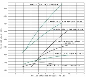
This method is not preferred because it requires precise measurement and it presumes a perfectly round tube. It also depends on the tube sheet hole not enlarging. The use of torque vs. pull out strength curve for determining the necessary amount of roller expansion is on the increase. This is done by using a sample tube sheet of the same material and thickness as the full-sized condenser and with drilled holes with the same spacing and tolerance as the full-sized condenser or heat exchanger. Tube samples about 12 ” long are sealed at one end either by crimping and welding or by welding plugs in one end of the tube. The tubes are then roller expanded into holes at varying torques. The usual range for this test is 7 to 12 ft. lbs. When using a torque controlled air motor to drive the expander, it is important that it be calibrated correctly. This can be done either in the field or in the laboratory by using a portable prony brake such as the Coleco Power Tube Analyzer Model P-15 manufactured by Dresser Laboratories. For thin wall tubes, a five-roller expander with a thin gauge collar, such as the Wilson 72D, is recommended. Pull-out strengths are determined using a hydraulic tensile tester. The tubes can be either pulled from the plugged end or pushed from the expanded end. If the push-out method is used, a filler material such as sand should be placed inside the tube for the push rod to contact. It is important that the level of the filler material in the tube be below the roller expanded area and that the push rod is kept vertical and not in contact with the tube wall. If this is not done, erroneously high pull-out values will result. When the ratio O.D./ t is greater than 25, five roller expanders should be used. For lower ratios, three roller expanders are generally satisfactory.

When doing the roller expansion, both the tube ends and the tube sheet holes should be wiped clean of debris and soil. The presence of lubricating oil in the tube holes or on the tube’s outside surface can result in reduced pull-out strength and leak tightness of the finished roller expanded joint. It is preferable that the tube ends be wiped also with a solvent such as acetone or methyl ethyl ketone. Do not use chlorinated solvents or methanol. The expander should also be inspected for cleanliness and should be free of dirt or other foreign matter. The rolls and mandrel should be free to move and should be in good condition. Before inserting the expander into a tube, the shutoff torque should be confirmed by using the prony brake, then the expander should be properly lubricated with a water soluble lubricant, such as Wilson Expander Lube. A suitable air- powered expander drive is Wilson Series 3A Torque-Air-Matic, Catalog No. 40511, having a speed of 450 rpm and a maximum torque of 18 foot pounds. The suggested torque for different tube sheet materials is shown in Figure 11. The torque should be checked hourly using the prony brake. Additional lubricant should be used on the expander as required. The rolls and mandrel should be inspected periodically for chipped rolls and/or mandrel damage. Damaged pieces should be replaced immediately. Roller expanded joints are not recommended for use with explosively bonded tube sheets. The material used as the cladding is usually relatively thin, 3/16 ” -1/4 ” max., and is almost always softer and lower in strength than the tube material. Such roller-expanded joints have a history of leakage after short periods of time. If the thickness of the cladding is increased so that leak integrity is not a problem, the economics usually favor a solid titanium plate.
Welding titanium in titanium fabrication
Titanium and most titanium alloys are readily weldable, using several welding processes. Properly made welds in the as-welded condition are ductile and, in most environments, are as corrosion- resistant as base metal. Improper welds, on the other hand, might be embrittled and less corrosion-resistant compared to base metal. The techniques and equipment used in welding titanium are similar to those required for other high-performance materials, such as stainless steels or nickel-base alloys. Titanium, however, demands greater attention to cleanliness and to the use of auxiliary inert gas shielding than these materials. Molten titanium weld metal must be totally protected from contamination by air. Also, hot heat-affected zones and root side of titanium welds must be shielded until temperatures drop below 800°F (427°C). Titanium reacts readily with air, moisture, grease, dirt, refractories, and most other metals to form brittle compounds. Reaction of titanium with gases and fluxes makes common welding processes such as gas welding, shielded metal arc, flux cored arc, and submerged arc welding unsuitable. Likewise, welding titanium to most dissimilar metals is not feasible, because titanium forms brittle compounds with most other metals; however, titanium can be welded to zirconium, tantalum and niobium. In spite of the precautions which need to be taken, many fabricators are routinely and economically welding titanium, making sound, ductile welds at comparable rates to many other high performance materials. One of the important benefits of welding the commercially pure grades of titanium is that they are over 99% pure titanium and there is no concern for segregation. The same is true of weld wire or rod in commercially pure grades.
Welding Environment
Most titanium welding today is done in the open fabrication shop, although chamber welding is still practiced on a limited basis. Field welding is common. Wherever the welding is done, a clean environment is necessary in which to weld titanium. A separate area, specifically set aside for the welding of titanium, aids in making quality welds. This area should be kept clean and should be isolated from dirt-producing operations such as grinding, torch cutting and painting. In addition, the welding area should be free of air drafts and humidity should be controlled.
Welding Processes
Titanium and its alloys are most often welded with the gas tungsten-arc (GTA or TIG) and gas metal-arc (GMA or MIG) welding processes. Resistance, plasma arc, electron beam and friction welding are also used on titanium to a limited extent. All of these processes offer advantages for specific situations. However, the following discussion will be concerned primarily with GTA and GMA welding. Many of the principles discussed are applicable to all processes.
Gas Tungsten-Arc (GTA) and Gas Metal-Arc (GMA) Welding
The GTA process can be used to make butt joints without filler metal in titanium base sheet of up to about 1/8-inch thickness. Heavier sections generally require the use of filler metal and grooved joints. Either the GTA or GMA welding process can be used, although GMA welding is more economical for sections heavier than about one-half inch. If the GTA process is used, care should be exercised to prevent contact of the tungsten electrode with the molten puddle, thereby preventing tungsten pickup.
Power Supply
A conventional power supply, connected d.c. straight polarity (DCSP), is used for GTA welding of titanium. Reverse polarity (DCRP) is used for GMA welding of titanium. A remote controlled contactor allows the arc to be broken without removal of the torch from the cooling weld metal, thereby maintaining inert gas shielding. Foot operated current and contactor control, high frequency arc starting and shielding gas timers are other desirable features.
Welding Torch
A water-cooled welding torch, equipped with a 3/4-inch ceramic cup and a gas lens, is recommended for GTA welding of titanium. A one-inch cup may be required for GMA welding. Thoriated tungsten electrodes (usually 2% thoria) are recommended for GTA welding of titanium. Pointed electrodes (end blunted) help to control arc characteristics. The smallest diameter electrode which can carry the required current should be used.
Inert Gas Shielding
Protection needs to be provided to titanium weldments on cooling down to about 800°F (427°C) as well as to the molten weld puddle in order to prevent contamination by air. During GTA and GMA welding, argon or helium shielding gases of welding grade with dewpoint of -50°F (-46°C) or lower are used to provide the necessary protection. Separate gas supplies are needed for:
- Primary shielding of the molten weld
- Secondary shielding of cooling weld deposit and associated heat- affected
- Backup shielding of the backside of weld and associated heat- affected
Primary Shielding
Primary shielding of the molten weld puddle is provided by proper selection of the welding torch. Standard water-cooled welding torches equipped with large (3/4 or 1-inch) ceramic cups and gas lenses, are suitable for titanium. The large cup is necessary to provide adequate shielding for the entire molten weld puddle. The gas lens provides uniform, nonturbulent inert gas flow. Argon is generally used in preference to helium for primary shielding at the torch because of better arc stability characteristics. Argon-helium mixtures can be used if higher voltage, hotter arc and greater penetration are desired. Manufacturer’s recommended gas flow rates to the torch should be used. Flow rates in the vicinity of 20 cfh have proven satisfactory in practice. Excess flow to the torch may cause turbulence and loss of shielding. The effectiveness of primary shielding should be evaluated prior to production welding. An arc can be struck on a scrap piece of titanium with the torch held still and with shielding gas only on the torch. The shielding gas should be continued after a molten puddle forms and the arc is extinguished, until the weld cools. Uncontaminated, i.e., properly shielded, welds will be bright and silvery in appearance.
Secondary Shielding
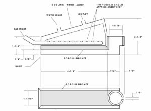
Secondary shielding is most commonly provided by trailing shields. The function of the trailing shield is to protect the solidified titanium weld metal and associated heat-affected zones until temperature reaches 800°F (427°C) or lower. Trailing shields are generally custom-made to fit a particular torch and a particular welding operation. A schematic of a trailing shield, useful for flat sheet or plate welding of titanium, is shown in Figure 13. Design of the trailing shield should be compact and allow for uniform distribution of inert gas within the device. The possible need for water-cooling should also be considered, particularly for large shields. Porous bronze diffusers have provided even and nonturbulent flow of inert gas from the shield to the weld.
Backup Shielding
The prime purpose of backup devices is to provide inert gas shielding to the root side of welds and their heat-affected zones. Such devices often look much like trailing shields and may be hand-held, or clamped or taped into position. Water-cooled copper backup bars (or massive metal bars) may also be used as heat sinks to chill the welds. These bars are grooved, with the groove located directly below (or above) the weld joint. About 10 cfh of inert gas flow per linear foot of groove is required for adequate shielding. Makeshift shielding devices are often employed very effectively with titanium welds under shop or field conditions. These include use of plastic to completely enclose the workpiece and flood it with inert gas. Likewise, aluminum or stainless steel foil “ tents,” taped over welds and flooded with inert gas, are used as backup shields. When such techniques are used, it is important that all air, which will contaminate welds, be purged from the system. An inert gas purge equal to ten times the volume of the air removed is a good rule-of-thumb for irregular spaces. A moderate rate of inert gas should be maintained until the weld is completed. Argon is generally selected in preference to helium for use in trailing shields and backup devices, primarily because of cost but also because it is more dense. Helium, with its lower density, is sometimes used for trailing or backup shielding when the weld is above the device. It is important that separate flow controls are available for primary, secondary and backup shielding devices. Timer- controlled pre-purge and post-purge of torch shielding, and solenoid valves with manual switches interlocked with the welding current for secondary and backup shielding are also useful.
Joint Design and Preparation
Weld joint designs for titanium are similar to those for other metals (Table 22). The joint design selected for titanium however, must permit proper inert gas shielding of both root and face during welding as well as post-weld inspection of both sides of the weld. The joint surfaces must be smooth, clean and completely free of contamination. All burn marks produced by grinding or mechanical filing should be removed by filing. Likewise, burrs and sharp edges should be removed with a sharp file. The use of sandpaper or steel wool, which leave particles behind, can be a source of contamination. Good joint fit-up is important for titanium. Uniform fit-up minimizes burn-through and controls underbead contour. Poor fit-up may increase the possibility of contamination from air trapped in the joint, particularly with butt joints on light gauge material. Maintenance of joint opening during welding is important. Clamping to prevent joint movement during welding is recommended. If tack welds are used, the same care in cleaning and inert gas shielding must be exercised, as with any and all titanium welds, to prevent contamination. Any cracked or contaminated tack welds must be removed before final welding.
Cleaning
Before welding titanium, it is important that weld joints and weld wire be free of mill scale, dirt, dust, grease, oil, moisture and other potential contaminants. Inclusion of these foreign substances in titanium weld metal could degrade properties and corrosion resistance. Weld wire is clean as packaged by the manufacturer. If wire appears to be dirty, wiping with a non-chlorinated solvent, prior to use, is good practice. In severe cases, acid cleaning may be required. All joint surfaces and surfaces of base plate for a distance of at least an inch back from the joint need to be cleaned. Normal pickled mill surfaces generally require only scrubbing with household cleaners or detergents, followed by thorough rinsing with hot water and air drying. Alternatively, wiping of weld joints and adjacent areas with non- chlorinated solvents such as acetone, toluene, or methyl ethyl ketone (MEK), using clean lint-free cloths or cellulose sponges, is acceptable, provided no residue remains. The solvents are particularly effective in removing traces of grease and oil. Solvent cleaning should be followed by wire brushing, using a new stainless steel brush. Under no circumstances should steel brushes or steel wool be used on titanium because of the dangers to corrosion resistance which embedded iron particles pose.

Light oxide films, as might result from heating in the range 600°-800°F (316- 427°) for forming operations, can be removed by brushing with a new stainless steel wire brush. Light grinding, draw filing and acid pickling are also effective. An acceptable pickle bath for titanium is 35 vol.% nitric (70% concentration), and 5 vol.% hydrofluoric acid (48% concentration) used at room temperature. Dipping of weld joint areas for 1 to 15 minutes (depending on the activity of the bath) should be sufficient. A cold water rinse to remove acid, followed by a hot water rinse to facilitate drying, completes the cleaning. Heavy scale and oxygen-contaminated surfaces, such as might be present after a high temperature heat treatment, are best removed by mechanical means. Grinding, and sand or grit blasting are commonly used. Molten caustic baths, although useful, require care to minimize the possibility of hydrogen pickup. After scale removal, an acid pickle should be used to remove all residue and improve surface appearance. Once cleaned, joints should be carefully preserved. Handling should be minimized and welding should commence as soon after cleaning as is possible. When not being worked on, weld joints should be kept covered with paper or plastic to avoid accumulation of contaminants.
Filler Metal Selection
Titanium welding wire is covered by AWS A5.16-70 Specification ( “Titanium and Titanium-Alloy Bare Welding Rods and Electrodes” ). It is generally good practice to select a filler metal matching the properties and composition of the titanium base metal grade. However, for both commercially pure grades and alloys, selecting a weld wire one strength level below the base metal is also done. Special situations may require a different grade of filler wire to give desired combination of joint properties. For instance, several options are available for use with titanium. The low interstitial grade is useful where high weld ductility, such as is required in cryogenic applications, is needed.
Welding Parameters
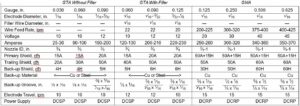
Guideline parameters for machine welding titanium are given in Table 24. These guidelines were developed on automatic equipment with backup bar, trailing shield and hold-down shoes. Parameters for manual welding are similar under similar welding conditions. If slower welding speeds are desirable, amperage must be reduced proportionately. Generally speaking, the lowest heat input consistent with good weld properties is desirable in welding titanium. It is good practice to weld test samples to optimize parameters for a particular welding application before committing material and manpower to the job.
Welding Technique
In addition to clean joints and weld wire, proper parameters, and proper inert gas shielding, welder technique requires attention when titanium is being welded. Improper technique can be a source of weld contamination. Before starting an arc in welding titanium, it is good practice to prepurge torch, trailing shield and backup shield to be sure all air is removed. Whenever possible, high frequency arc starting should be used. Scratch starting with tungsten electrodes is a source of tungsten inclusions in titanium welds. On extinguishing the arc, the use of current downslope and a contactor, controlled by a single foot pedal, is encouraged. Torch shielding should be continued until the weld metal cools below 800°F (427°C). Secondary and backup shielding should also be continued. A straw or blue color on the weld is indicative of premature removal of shielding gas. Preheating is not generally needed for titanium shop welds. However, if the presence of moisture is suspected, due to low temperature, high humidity, or wet work area, preheating may be necessary. Gas torch heating (slightly oxidizing flame) of weld surfaces to about 150°F (66°) is generally sufficient to remove moisture. The arc length for welding titanium without filler metal should be about equal to the electrode diameter. If filler metal is added, maximum arc length should be about 1-1/2 times the electrode diameter. Filler wire should be fed into the weld zone at the junction of the weld joint and arc cone. Wire should be fed smoothly and continuously into the puddle. An intermittent dipping technique causes turbulence and may result in contamination of the hot end of the wire on removal from the shield. The contaminants are then transferred to the weld puddle on the next dip. Whenever the weld wire is removed from the inert gas shielding, the end should be clipped back about 1/2-inch to remove contaminated metal. Interpass temperatures should be kept low enough, such that additional shielding is not required. Cleaning between passes is not necessary if the weld bead remains bright and silvery. Straw or light blue weld discoloration can be removed by wire brushing with a clean stainless steel wire brush. Contaminated weld beads, as evidenced by a dark blue, gray or white powdery color, must be ompletely removed by grinding. The joint must then be carefully prepared and cleaned before welding again.
Evaluating Weld Quality
Prior to making production welds on titanium, procedures and techniques should be closely evaluated. For pressure vessel construction, the ASME Boiler and Pressure Vessel Code, Section IX (Welding Qualification), details procedure and performance tests which must be met. Tensile and bend tests on trial welds made under conditions intended for production are the acceptance criteria. Impact or notch tensile tests may also be required, particularly for low temperature applications. Once good procedures are established, as evidenced by tensile and bend tests, they should be strictly followed in subsequent production welding.
Bend tests evaluate ductility. For this reason, the bend test made on pre- production trial welds or on extensions of production welds made for that purpose, provides a good evaluation of weld quality. A bend sample in which the weld is positioned perpendicular to the bend axis assures uniform straining of weld metal and heat-affected zones, thereby giving more meaningful results. Table 25 lists weld bend radii for various titanium alloys. Good quality welds should be capable of being bent to the indicated radii without cracking. During titanium fabrication process problems with titanium welds are generally a result of contamination due to inadequate shielding. The color of welds can be used as an indicator of shielding effectiveness and, indirectly, weld quality. Thus, any indication of the quality level of a single pass titanium weld is readily apparent to the welder and any inspector. Weld colors reflect the degree to which the weld was exposed to oxygen (air) at elevated temperature. A bright silvery metallic luster generally can be taken as an indication of a good weld, provided the weld joint was clean and good techniques were followed. The presence of other colors, as indicated in the following list, represents various degrees of surface and weld contamination and require attention.
Probable Cause
Weld Color and Treatment
Light Straw Surface oxide. Remove by wire Dark Straw brushing with new stainless steel Light Blue wire brush.
Dark Blue Metal contamination. Welds Gray Blue should be removed and done Gray over after corrections in shielding
are made.
White Metal contamination. Welds (loose deposit) should be removed and done over after corrections in shielding are made.
Hardness measurements on weld vs. base metal are also sometimes used as an indicator of weld quality. Normally, uncontaminated weld hardness is no more than 30 points greater on the Knoop, Vickers or Brinell hardness scales (5 points Rockwell B) than the hardness of base metal of matching composition. It should be recognized that heat-to-heat variation in chemistry, within specifications, can result in hardness differentials somewhat higher than 30 Knoop or Brinell without any contamination. In any event, high weld hardness should be cause for concern because of the possibility of contamination. The ASME Code suggests that, if titanium weld metal hardness is more than 40 BHN greater than base metal hardness, excessive contamination is possible. Substantially greater hardness differential necessitates removal of the affected weld-metal area. The Code further specifies that all titanium welds be examined by liquid penetrant. In addition, full radiography of many titanium joints is required by the Code.
Resistance Welding
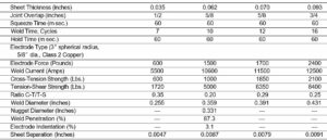
Resistance spot welding, seam welding and butt welding are performed on titanium in much the same manner as for other metals. As with arc welding, careful attention to cleanliness of metal surfaces and to protection of weld metal and heat affected zones from contamination by air are important. Preparation of titanium for resistance spot or seam welding is similar to that for other metals. The surface must be clean, free of scale, oxide, dirt, paint, grease, and oil. Cleaning of mill surfaces with commercial, nonchlorinated solvents which leave no residue is satisfactory. Light oxide scale, such as is present after elevated temperature forming has been performed, should be removed by acid pickling or by wire brushing with a clean stainless steel wire brush. Inert gas shielding of resistance spot and seam welds is often not required. The close proximity of mating surfaces in combination with the very short duration of the resistance weld cycle and squeeze pressure all help to exclude air from the weld. If a deep blue, gray or whitish color develops on the surface of titanium after resistance spot or seam welding, consideration must be given to altering weld parameters or providing inert gas shielding. Equipment and parameters for resistance spot or seam welding titanium are the same as are required for austenitic stainless steel. Typical parameters which proved successful in spot welding sheet are given in Table 26. As with any welding procedure to be used on titanium, test resistance spot and seam welds should be made on titanium, prior to production welds. Tension-shear tests will help to determine quality of the welds made. Once parameters and procedures are verified as producing quality welds consistently, these should be adhered to strictly during production runs. Resistance butt welding and a variation- stud welding are interesting techniques which are sometimes used on titanium. Clean, oxide-free abutting surfaces are a must. Flow of current through the workpiece causes arcing and resistance heating, bringing temperature close to the melting point. At the proper temperature, the workpieces are forced together, pushing molten and plastic metal out of the joint. Successful welds have been made in air. However, inert gas shielding may be required for contamination-free welds. The resistance butt weld technique has been used to successfully join titanium to dissimilar metals such as copper alloys, steels and stainless steels as well as other titanium alloys. Test welds should be made and carefully analyzed to establish proper parameters to be followed on production welds.
Brazing Titanium
Several brazing techniques are applicable to titanium. These include induction brazing, resistance brazing and furnace brazing in an argon atmosphere or in vacuum. Torch brazing is not applicable to titanium. Since brazing techniques have the potential for contaminating titanium surfaces, cleanliness is important and consideration should be given to argon or helium gas shielding. Alloys for brazing titanium to itself or other metals are titanium-base (70Ti- 15Cu-15Ni), silver-base (various), or aluminum-base (various). The titanium- base alloy requires temperatures in the vicinity of 1700°F (927°C), whereas the silver and aluminum-base alloys require 1650°F (899°C) and 1100°-1250°F (593°-677°C) respectively. If corrosion resistance is important, tests should be run on brazed joints in the intended environment prior to use. TIMET’s research lab is available for consultation on titanium’s corrosion resistance in your environment. The titanium-base alloy reportedly offers superior resistance to atmospheric corrosion and saline environments.
Heat Treating Titanium
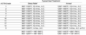
Heat treatment of titanium fabrications is not normally necessary. Annealing may be necessary following severe cold work if restoration of ductility or improved machinability are desired. A stress relief treatment is sometimes employed following severe forming or welding to avoid cracking or distortion due to high residual stresses, or to improve fatigue resistance.
Spot welding titanium:
Cleanliness of titanium parts to be heat treated is important because of the sensitivity of titanium to contamination at elevated temperatures. Titanium fabrications should be cleaned carefully prior to heating, using nonchlorinated solvents or a detergent wash, followed by a thorough water rinse. Handling following cleaning should be minimized to avoid potential surface contamination. As indicated in Table 27, unalloyed titanium are typically stress-relieved at about 1000°F (538°C) for 45 minutes and annealed at 1300°F (704°C) for two hours. A slightly higher stress relief temperature [1100°F (593°C), 2 hrs.] and annealing temperature [1450°F (788°C), 4 hrs.] are appropriate for the alloy. Air cooling is generally acceptable. Although no special furnace equipment or protective atmosphere is required for titanium, a slightly oxidizing atmosphere is recommended to prevent pickup of hydrogen. Direct flame impingement for extended periods, leading to temperatures in excess of 1200°F (649°C), should be avoided because of the potential for contamination and embrittlement. Hydrogen or cracked ammonia atmospheres, also, should never be used, because their use would lead to excessive hydrogen pick-up, and embrittlement. If a scale removal treatment, following a high temperature (1200°F; 649°C) anneal is not feasible, a vacuum or inert gas (dry argon or helium) atmosphere is recommended. Superficial surface discoloration, caused by annealing below 1200°F (649°C), may be removed by acid pickling in a 35% nitric acid – 5% hydrofluoric acid bath at 125°F (52°C). However, if long heating times or temperatures above 1200°F (649°C) have been used, a molten caustic bath or mechanical descaling treatment, followed by nitric- hydrofluoric acid pickling, is necessary to remove scale. Numerous surface treatments are applied to titanium for a variety of reasons. The prevention of galling and the improvement of corrosion, being perhaps, the most important reasons.
Prevention of Galling
Galling not only causes excessive wear on titanium but may also result in accelerated corrosion through fretting action. Simple lubrication, using graphite or molybdenum disulfide, is often sufficient to overcome galling. It is, therefore, possible to use titanium for moving parts or for parts in sliding contact with itself or other metals with light to moderate loads. Heavier loads, on the other hand, require hardened titanium surfaces. Commercially available case hardening techniques, such as plasma spraying, ion implantation, anodizing or nitriding, or coating techniques such as hard chromium electroplating or flame spraying of tungsten carbide and other hard, wear-resistant materials, are used. Such surface treatments possess the required qualities of good adherence plus wear and scuff resistance. However, careful consideration has to be given to the compatibility of the treated surface with the corrosive environment to which it will be exposed.
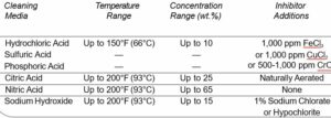
Cleaning of titanium eqipment
The efficiency of titanium surfaces can usually be maintained without elaborate cleaning procedures. There is generally no need to clean for corrosion protection as is sometimes required with stainless steel, nor does the thin oxide surface film in any way combine with cooling water to form heavy mineral deposits as sometimes occurs on copper-base alloys. Marine fouling of heat exchanger surfaces is sometimes controlled by chlorine injection. Titanium surfaces are totally unaffected by such treatments. Titanium surface condenser tubing is also kept clean in this way as well as by continuous cleaning systems utilizing rubber balls or nylon brushes, without deleterious effects. Acid cleaning of titanium surfaces to remove deposits is sometimes necessary. Conventional acid cleaning cycles can be used provided proper inhibitors are present. Organic inhibitors such as filming amines are not effective with titanium. Ferric ion as ferric chloride is very effective as an inhibitor for titanium in acid solutions. As little as 0.1 percent (by weight) ferric chloride will inhibit corrosion of titanium by hydrochloric acid, for instance. At ambient temperatures, as much as 25 percent (by weight) HCl inhibited with FeCl3 can be safely used on titanium. Nitric acid is an excellent passivating agent for titanium and may be used alone or with hydrochloric acid to clean titanium surfaces. See Table 28 for a more complete listing of recommended cleaning media, and proper inhibitor additions. The use of carbon steel wire brushes to remove deposits from titanium is not recommended. Likewise, carbon steel pipe or tube should not be used to clean out plugged titanium tubes. Pickup of imbedded or smeared iron particles from steel can render titanium susceptible to corrosion when the unit is placed back in service. Stainless steel or titanium wire brushes and pipe are preferred. Careful utilization of titanium’s unique properties will provide many years of maintenance-free service for fabricated equipment. Misapplication of titanium, the use of improper cleaning procedures and other abuses can lead to failure. On the other hand, careful use of some preventive measures, particularly those concerned with corrosion and galling resistance, can significantly extend the useful life of titanium equipment.
